

XPS 15 Heatsink // Personal Project
November, 2018
AutoCAD / Solidworks / Prototyping
The Dell XPS 15 series of laptops has had a throttling problem since at least the 9550, which was released in October 2015. This isn't uncommon with thin and light laptops, as their cooling performance is constrained by the overall thermal mass of the heatsink and the amount of air the fans can push through the fins. Since the release of the 9560, Razer and Gigabyte have released the Blade 15 and Aero 15X laptops, respectively, with a similar form factor and more powerful graphics chips, that both don't thermal throttle (at least not to the same extent).
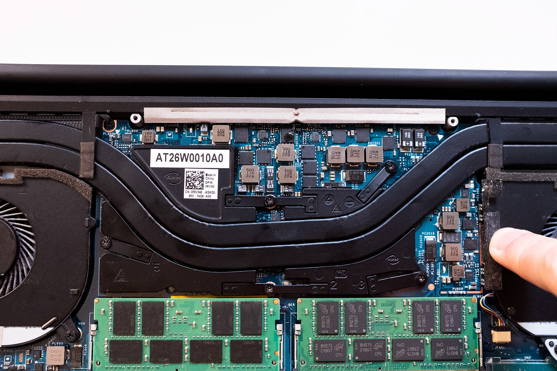
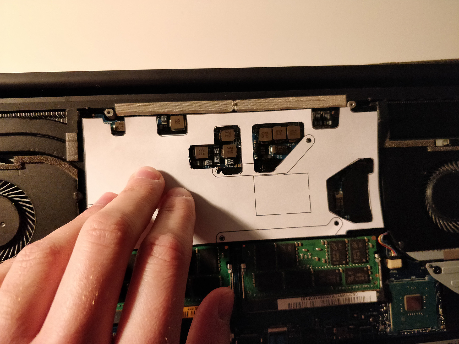
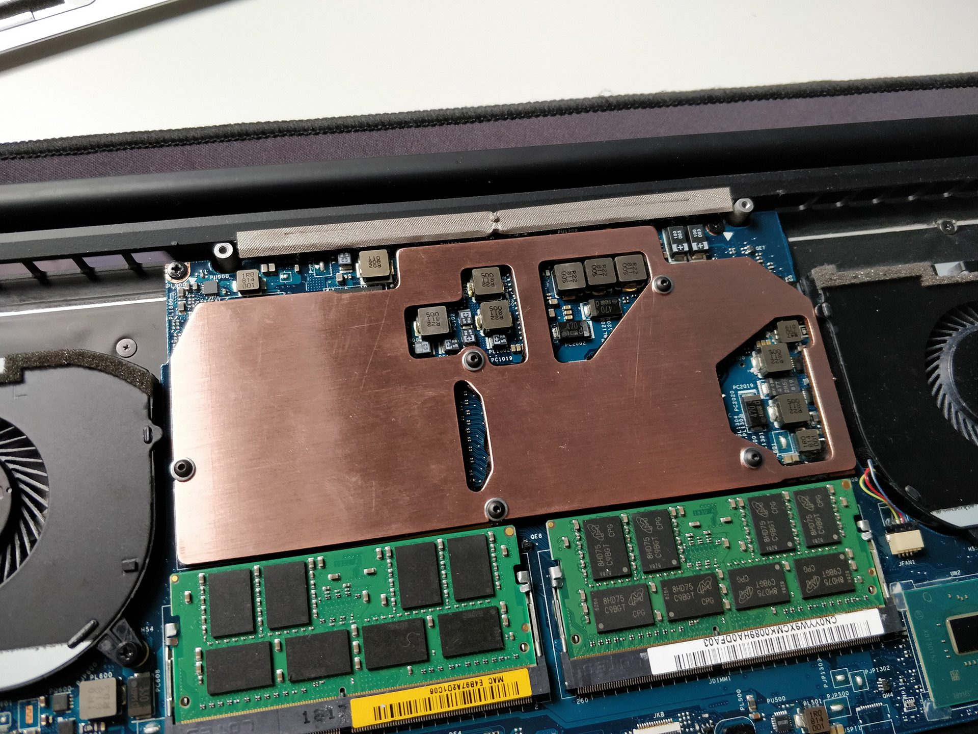
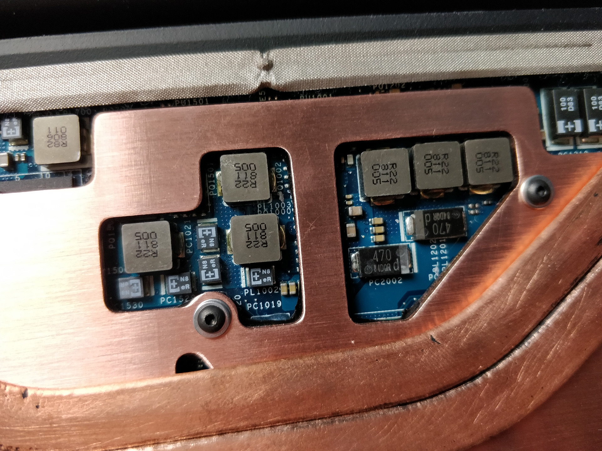
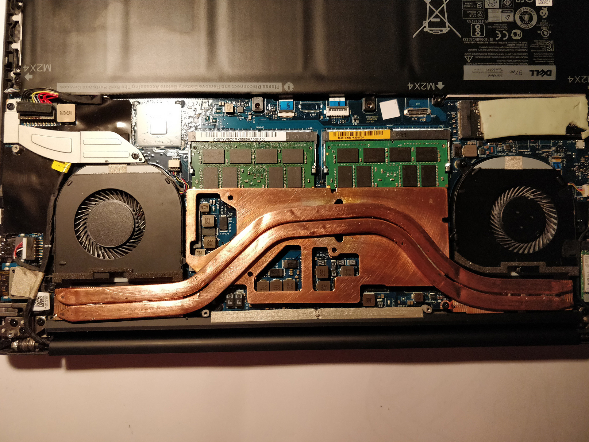
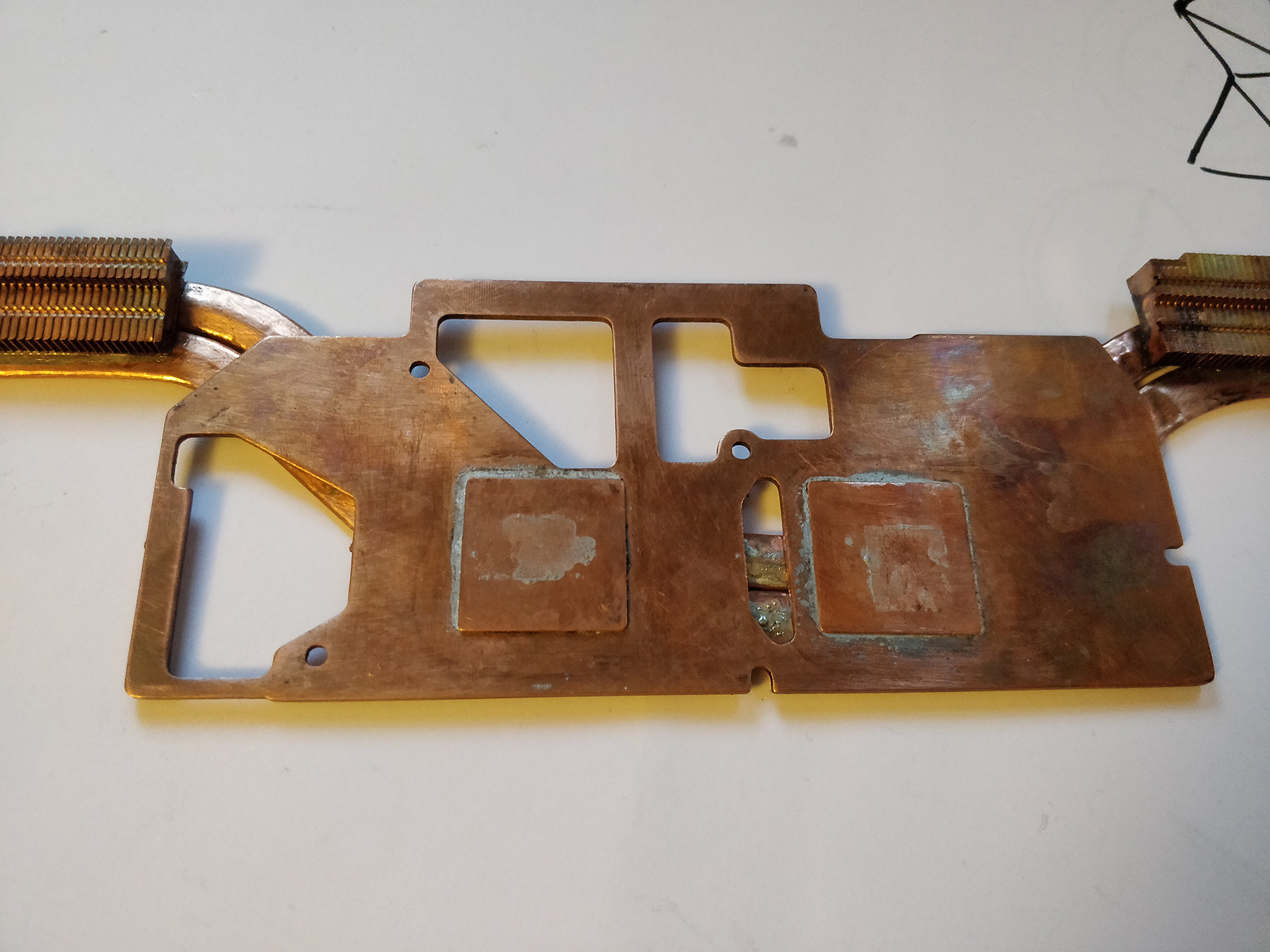
Dell ignored feedback from users regarding the throttling situation, with the VP and General manager of Alienware, Gaming XPS, Frank Azor, stating in a Tweet that the laptop, "isn't designed to be used for intensive tasks" (paraphrasing here a bit, he might've said gaming). This isn't something you want to hear when you put down a lot of money on a laptop that's sold as a desktop replacement. They used the same heatsink on the 9560 and the 9570 (my model), even though the 9570 included even more power hungry components. User iunlock on the NotebookReview forums devised a solution to the problem of thermal throttling in the 9560. By bridging the VRM MOSFETs (The small black chips seen in the first image below) to the bottom of the chassis using thermal pads, helping to prevent the CPU or GPU throttling under load for longer periods. The main problem with this solution is that it results in the bottom of the laptop heating up, which heats up the fan's intake air, and increases the CPU and GPU temperatures.
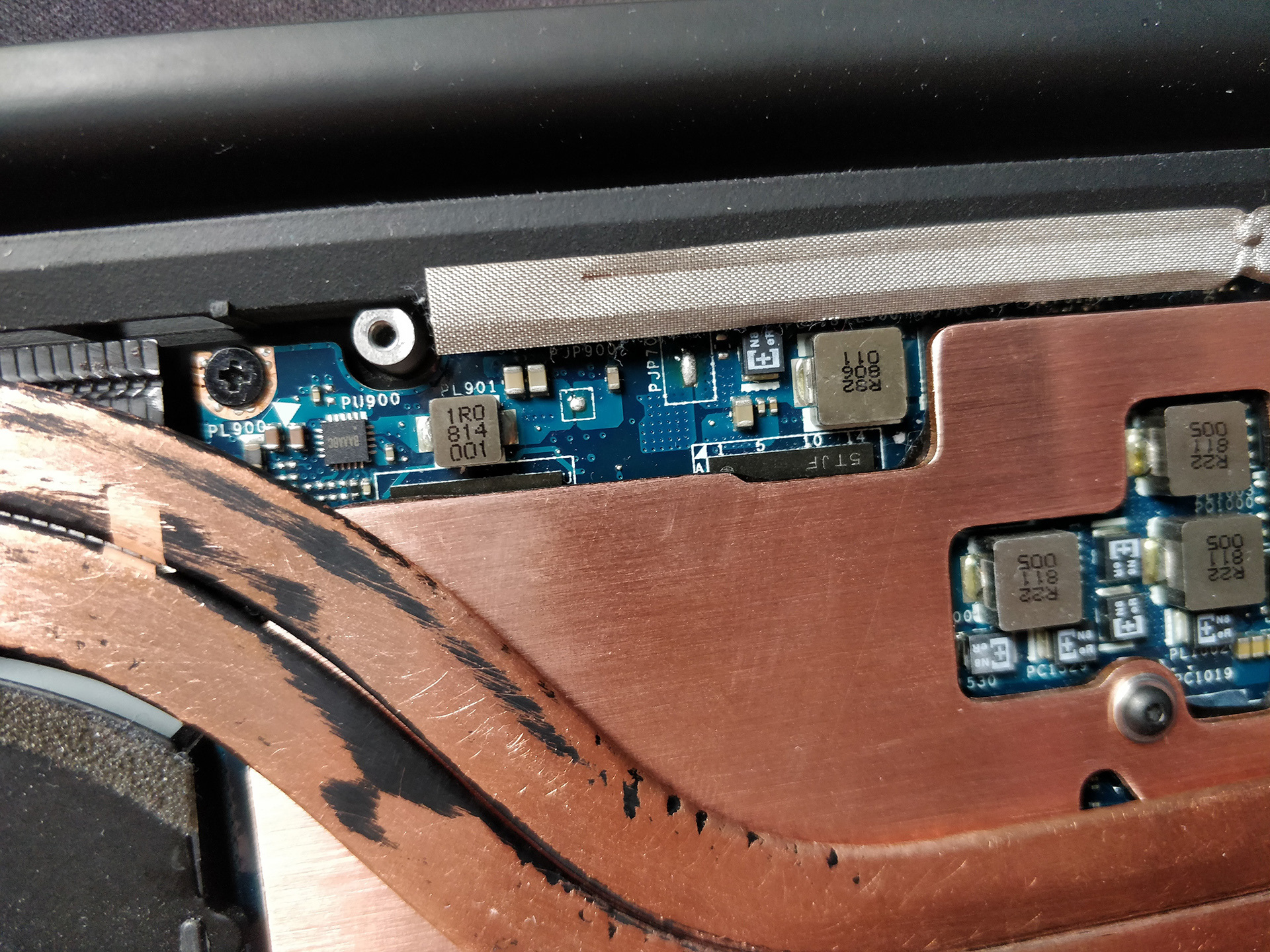
User Dialup David showed that without padding, and stressing both the CPU and GPU, the 9560's VRM MOSFETs hit 115°C and the heat spreads through the PCB, raising the temperature of surrounding components.
With the 9570 on full load, the CPU easily hits 97°C (Tj Max, the spec'd temperature ceiling from Intel) after the heatsink is saturated, causing it to throttle down to a lower clock speed. The GPU throttling isn't as much of a problem, as Dell have limited the GPU max temperature to 75°C, but loading both the CPU and GPU still results in the same VRM Throttling. In my case, this means longer render times, and FPS in games completely tanking to unplayable levels.
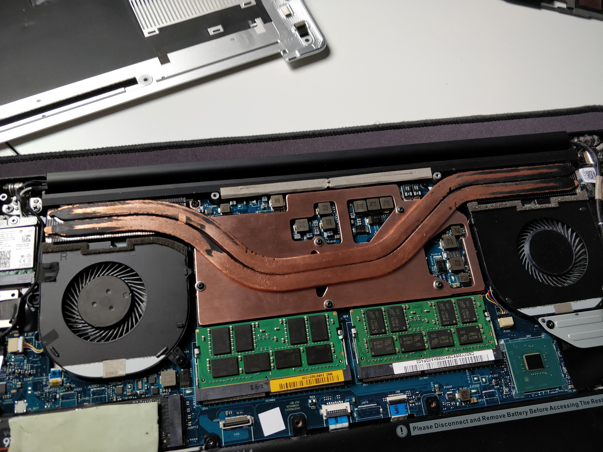
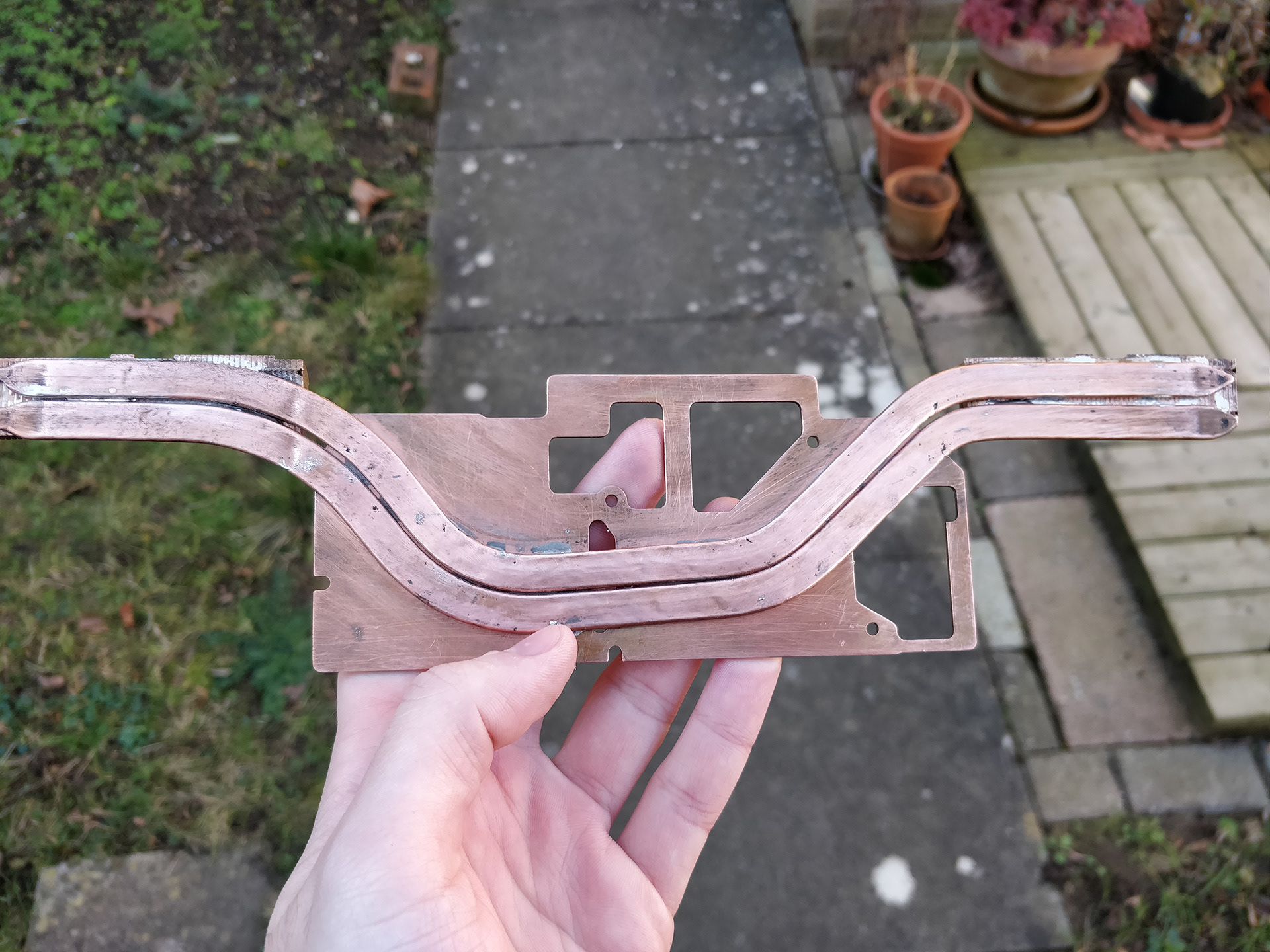
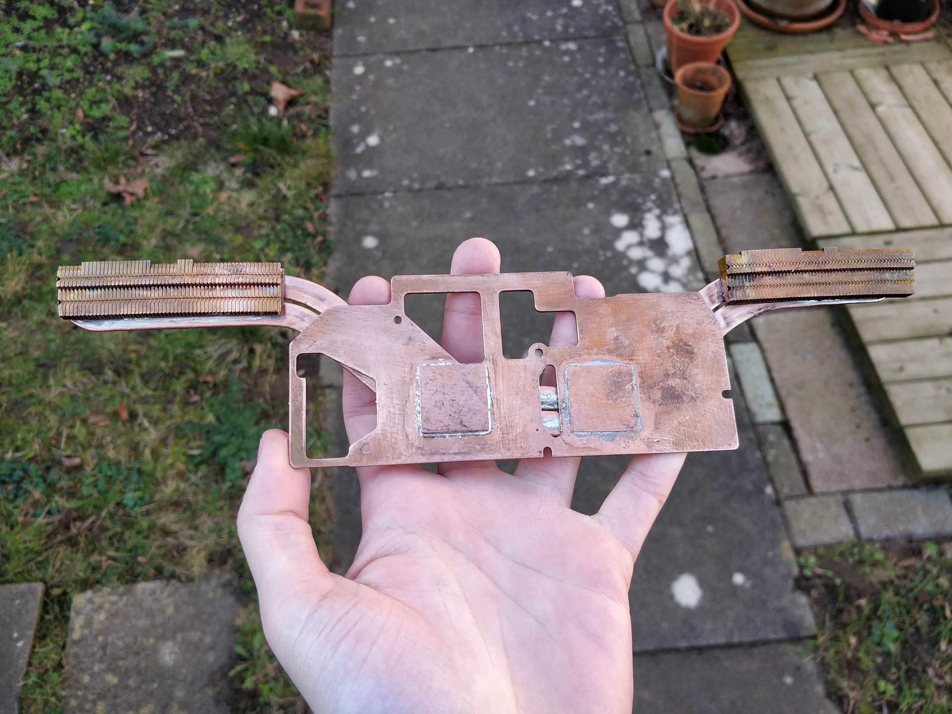
The aim of this project is to redesign the heatsink plate to effectively cool the CPU, GPU, and VRMs. Ideally, the fins will be replaced with copper versions, to aid in dissipation, but I'm using the stock heatpipes, as I believe that the high CPU and GPU temperatures can mostly be attributed to uneven heatsink mounting pressure, and the copper shims that sit between the components and heatpipes having insufficient contact, so the thermal paste has to carry the heat further than necessary. Ideally, I want it to keep all temperatures below that of the CPU, to reduce component wear, and increase the laptop's lifespan.
November 18th, 2018
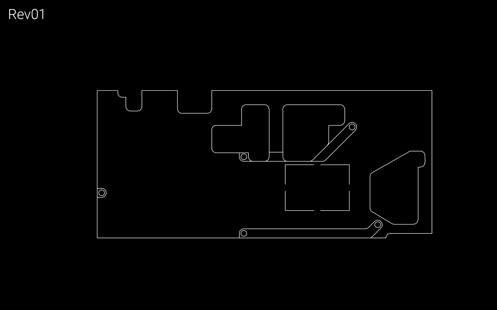
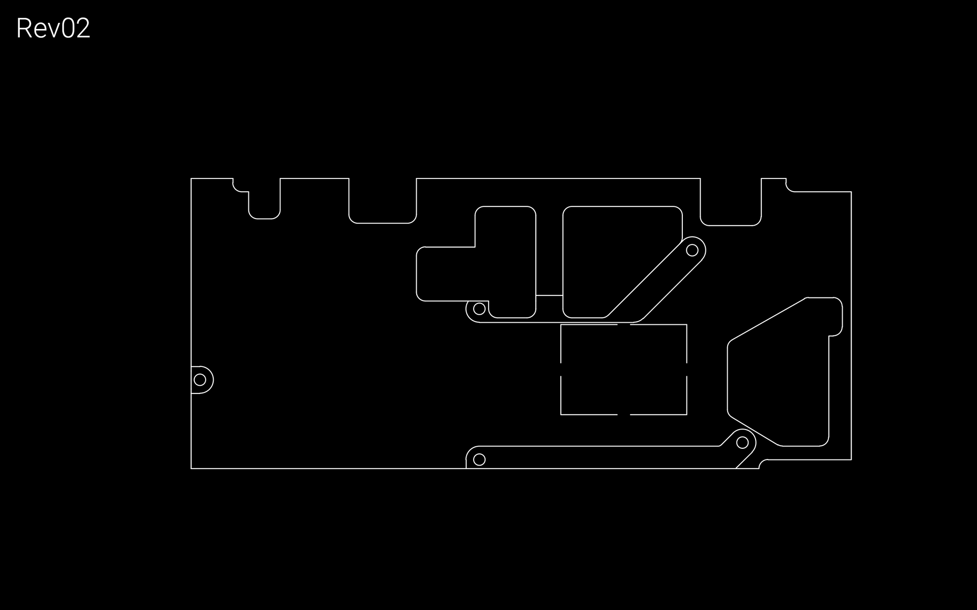
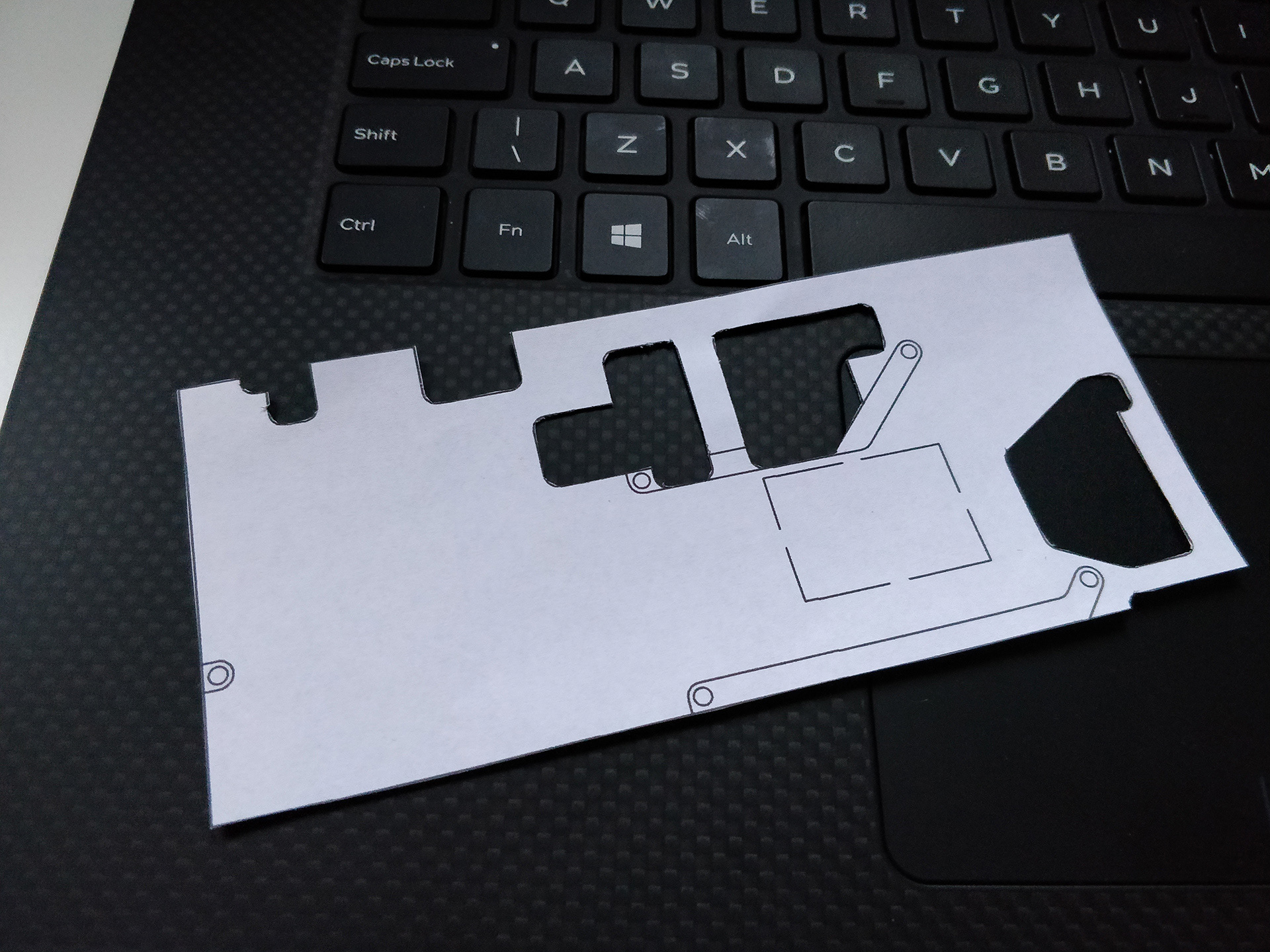
Started the project. Took measurements of the existing mounting mechanism and component layout, and produced the first drawing. Rev02 was done right after, adding cutouts for the components at the top right, and adjusting cutout sizes.
November 19th, 2018
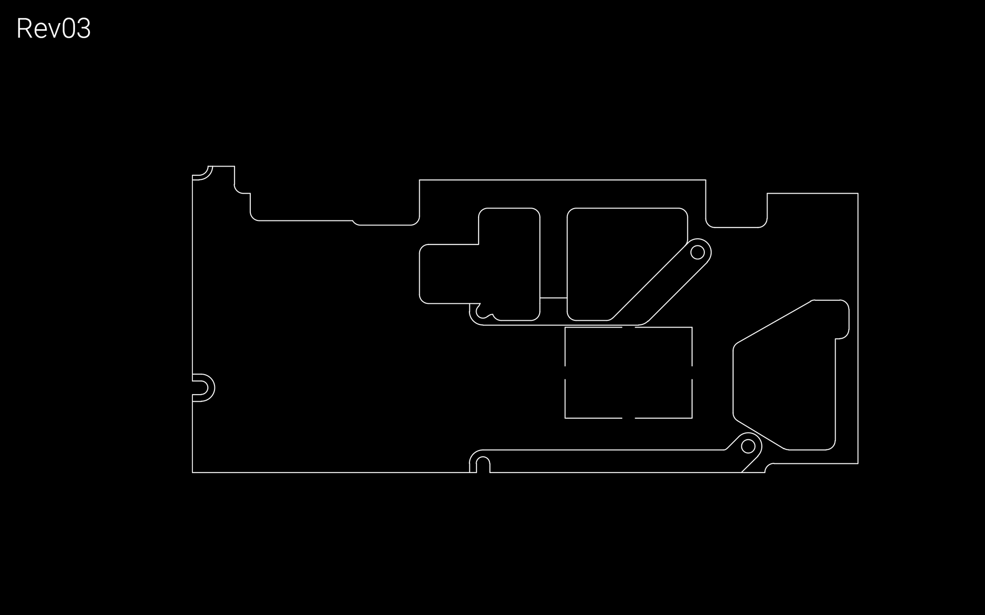
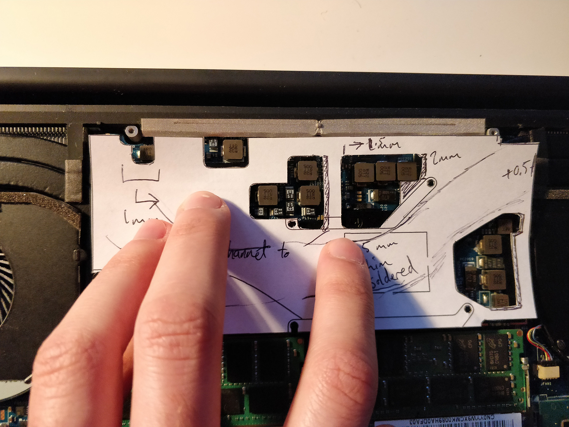
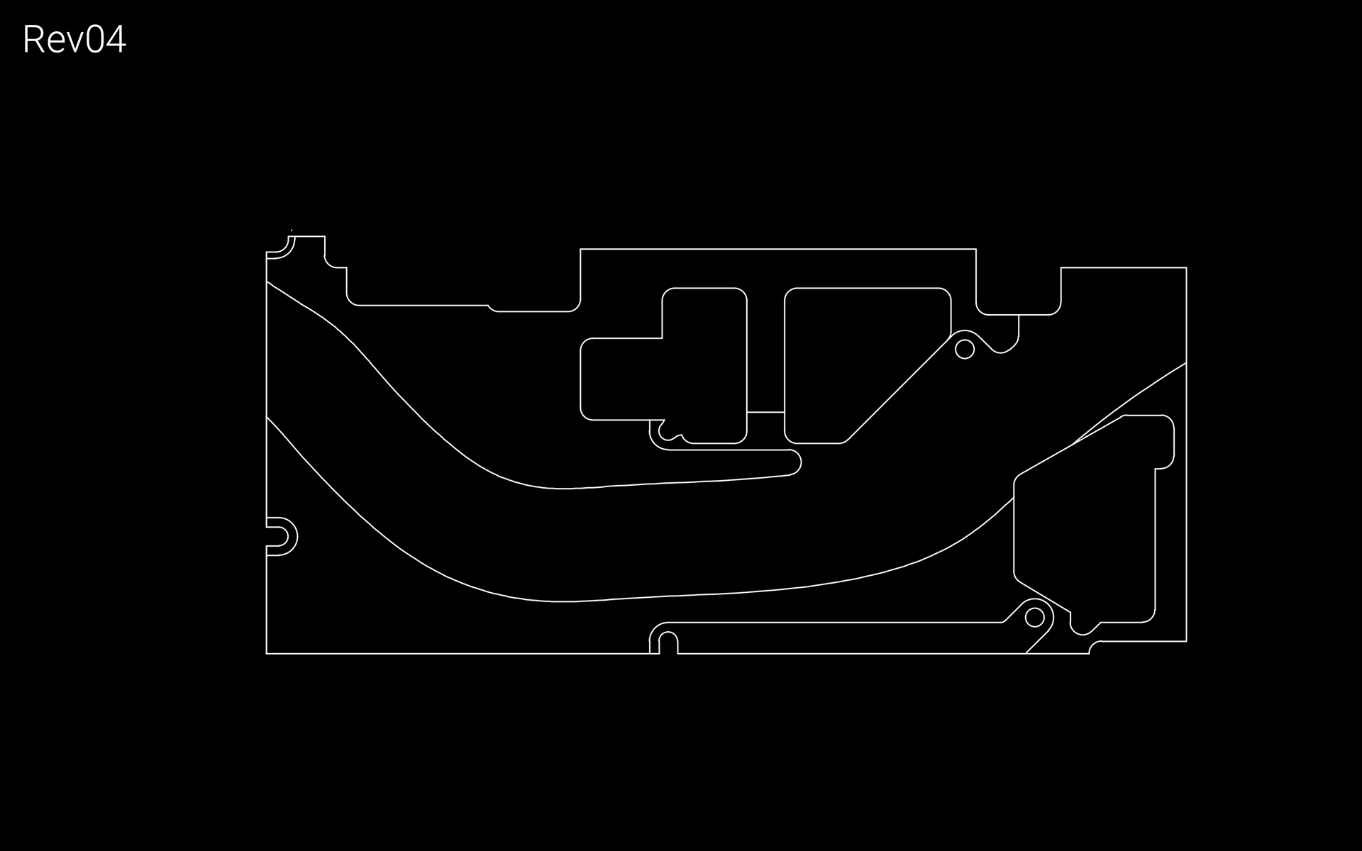
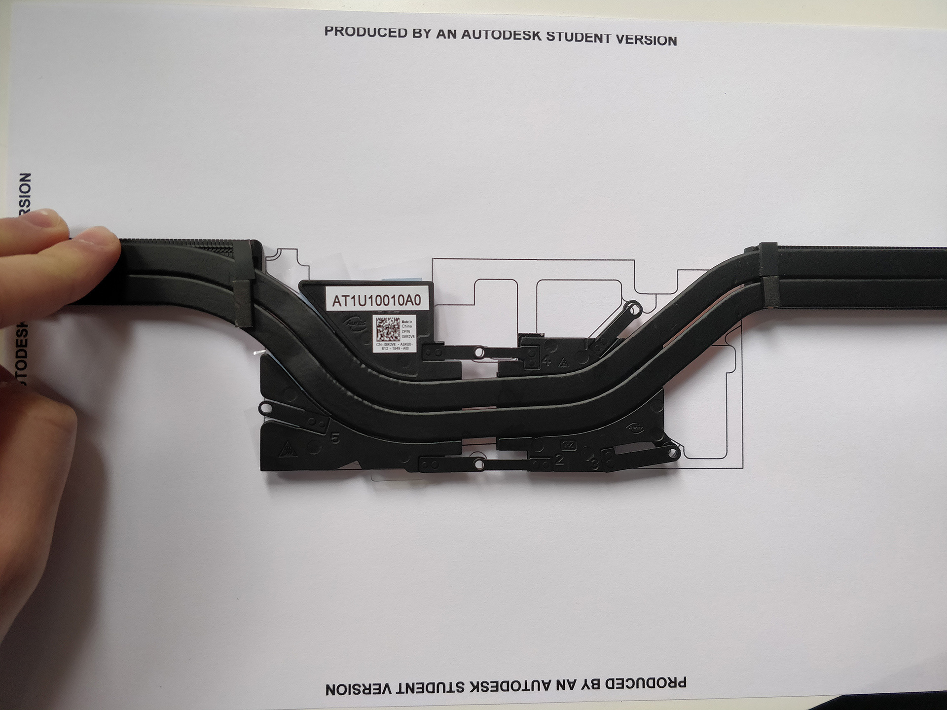
Rev03 added slotted holes close to edges, and extended the top left up to the motherboard mounting screw, helping to secure the heavier plate to the chassis. Rev04 kept all dimensions from Rev03, but added a channel for the heatpipes to sit in. I placed a printout of Rev03 on top of the heatsink, and traced the gap between the two heatpipes. I then took a photo of it, traced it in AutoCAD, and offset the line outwards both ways by the width of a heatpipe +1mm, to allow for mistakes in the line. Rev05 cleaned up the edges and removed some unnecessary material. This was also the point where I changed my mind about mounting system - opting to just screw the plate onto the mounts, rather than having similar retention brackets to the original.
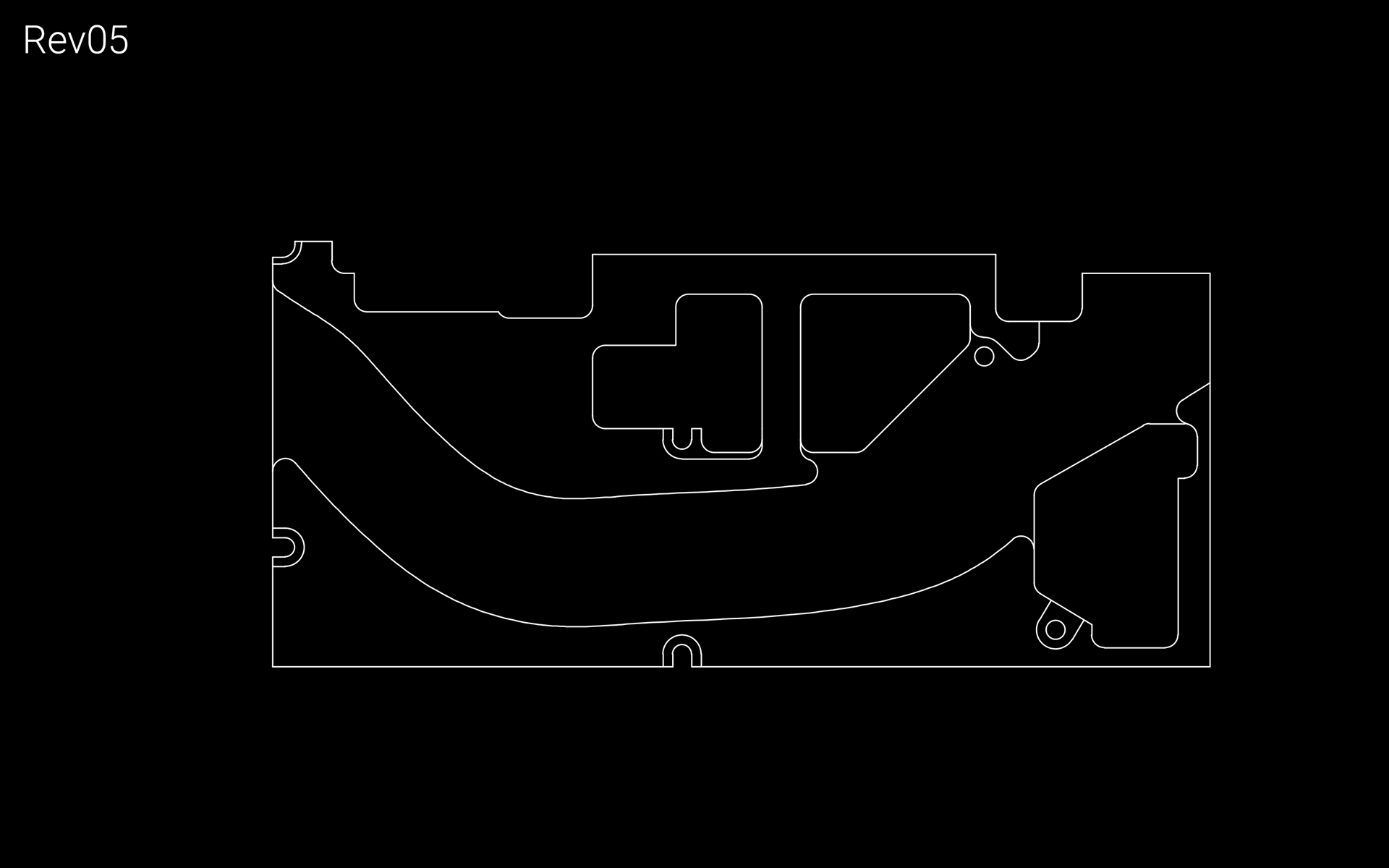
November 20th, 2018
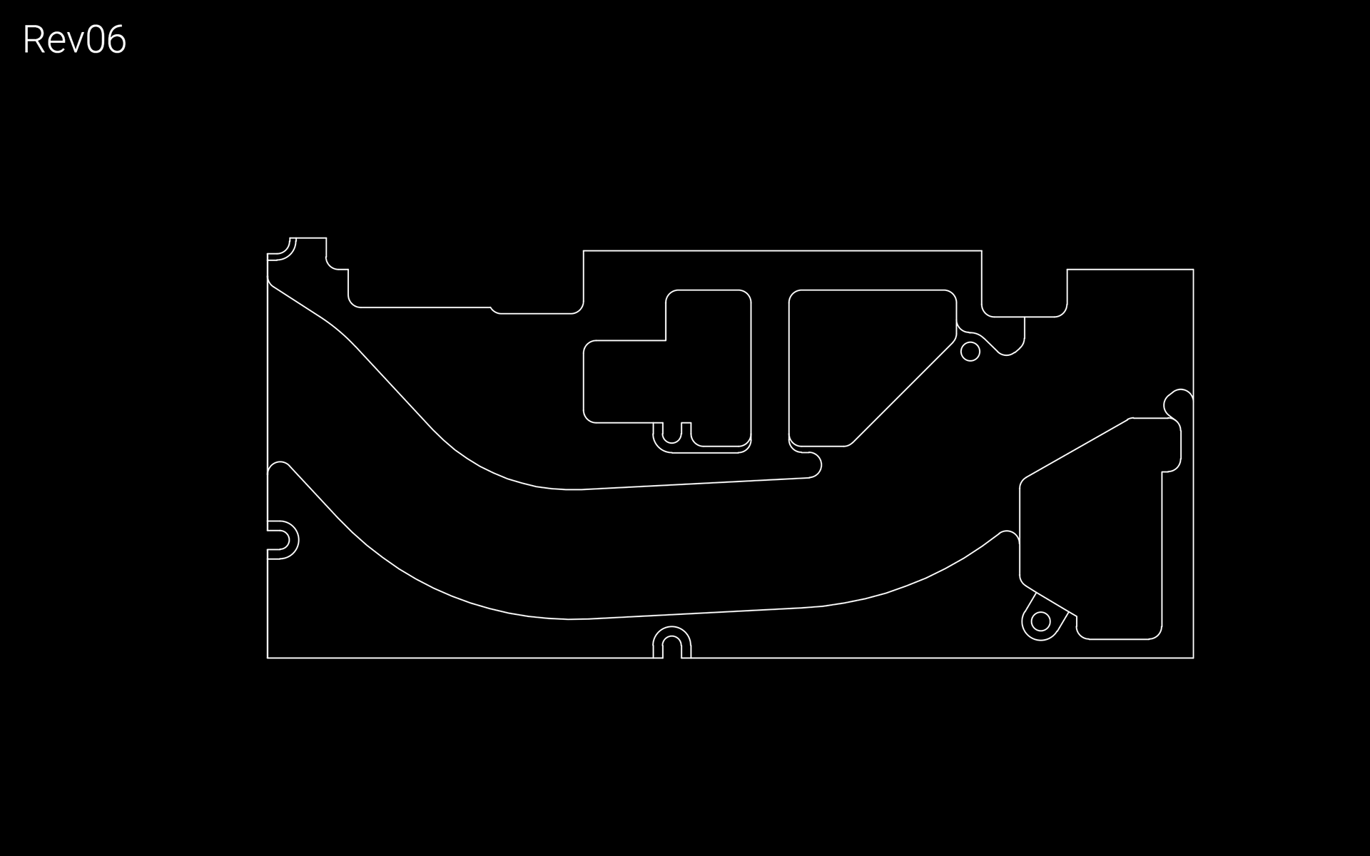
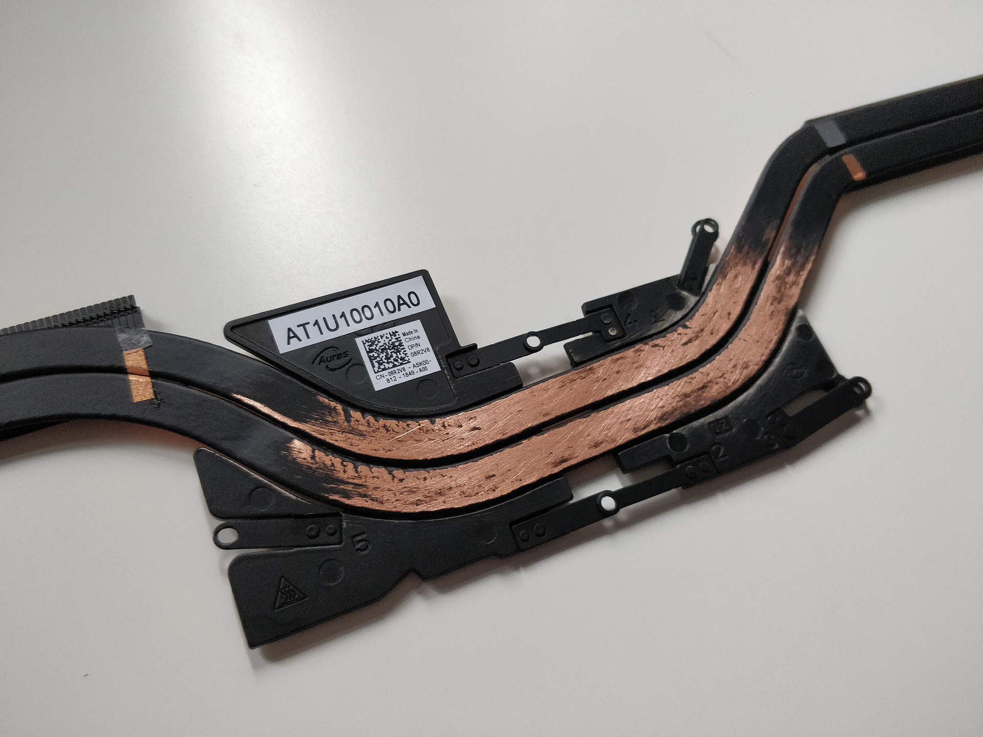
Rev05 widened the channel for the heatpipes. Heatink I ordered online turned up. Removed paint from the top of the heatpiptes, and desoldered the mount. Old mount works by sandwiching the aluminium plates between the heatpipes and shims. The lack of rigid connection between the two plates can result in warping. Rev06 widened the channel a bit more, and removed more material.
November 23rd, 2018
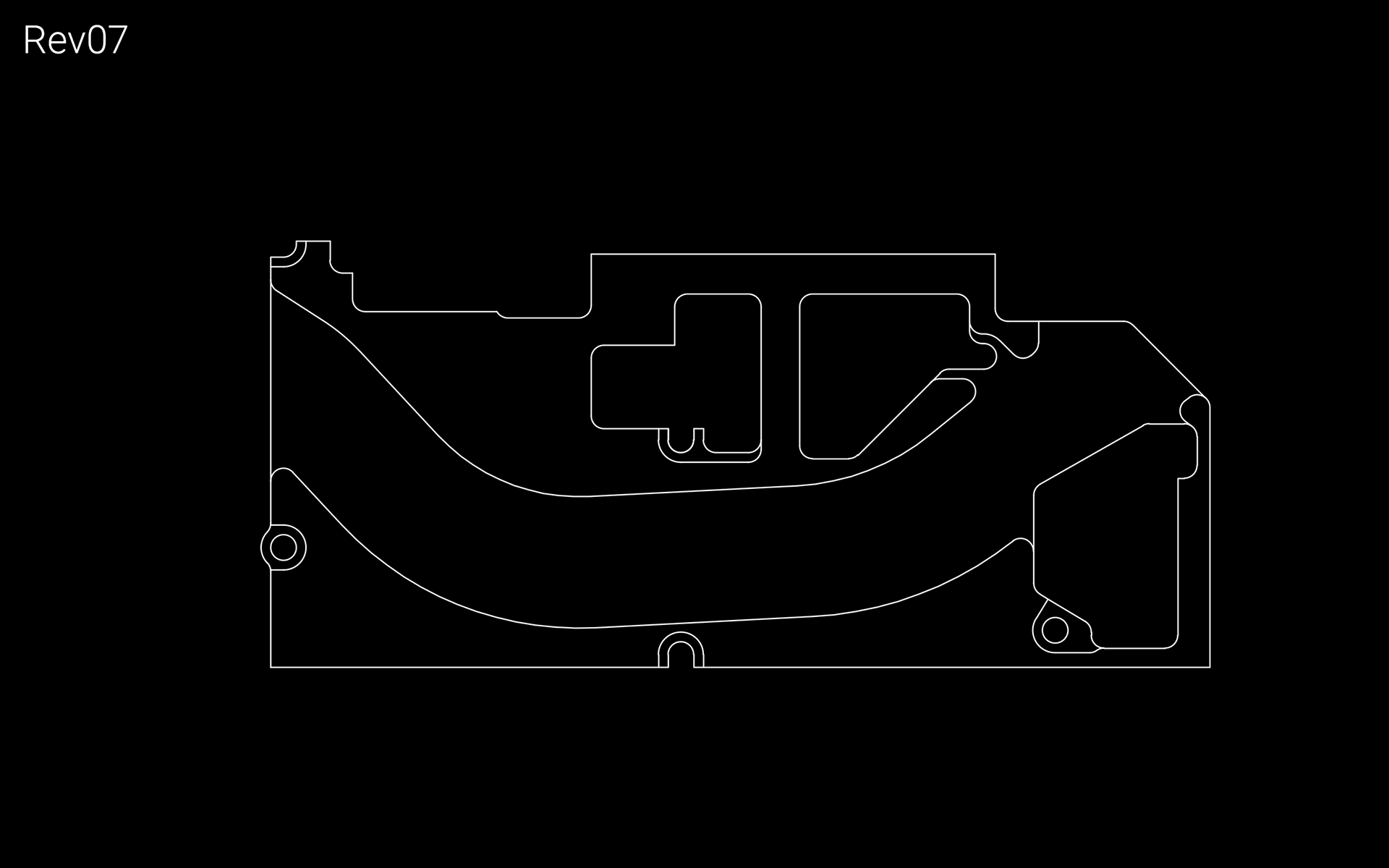
Rev07 widened the holes to 4mm diameter, as this was the smallest diameter bit available where I was originally going to get it CNC'd.
December 20th, 2018
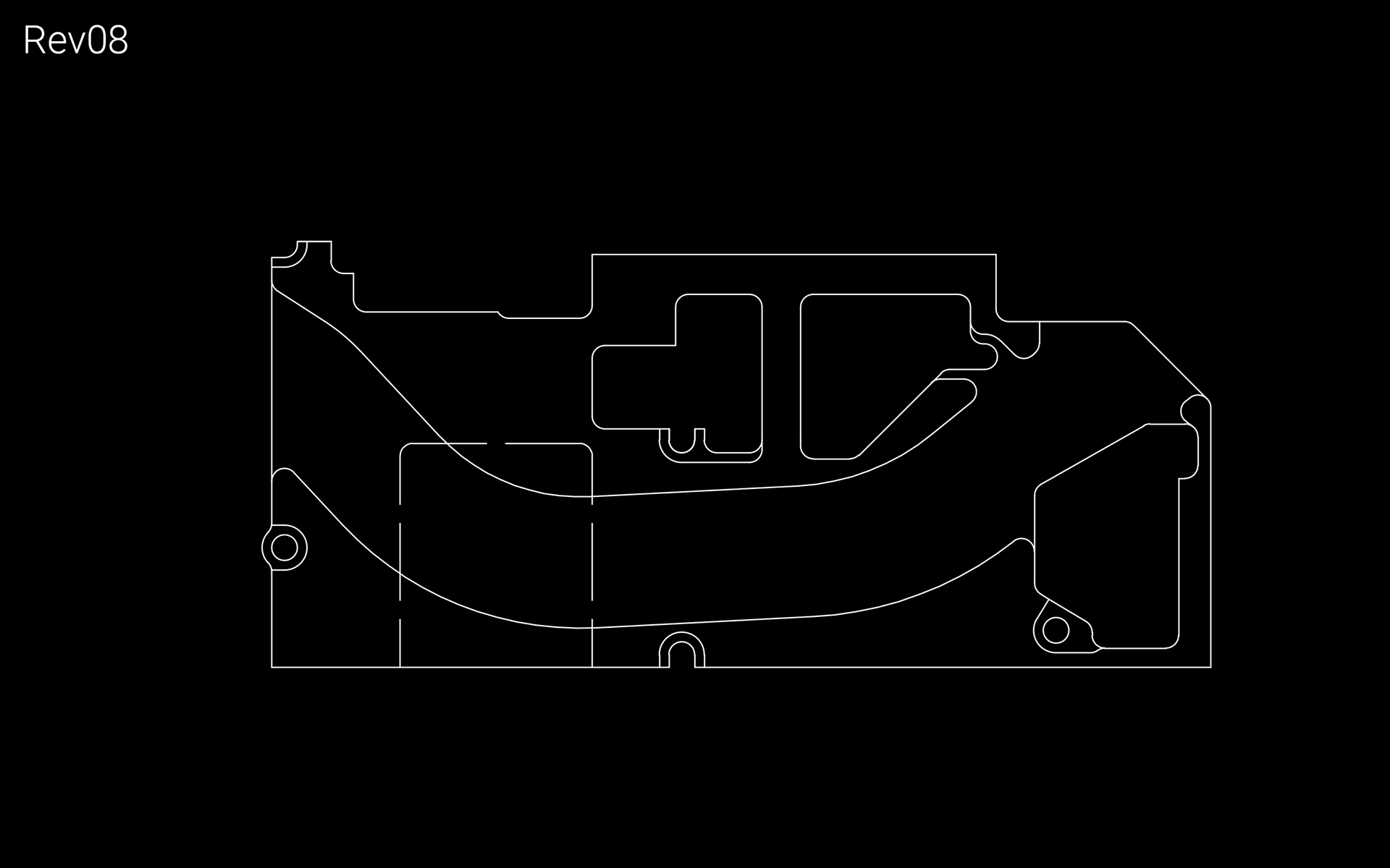
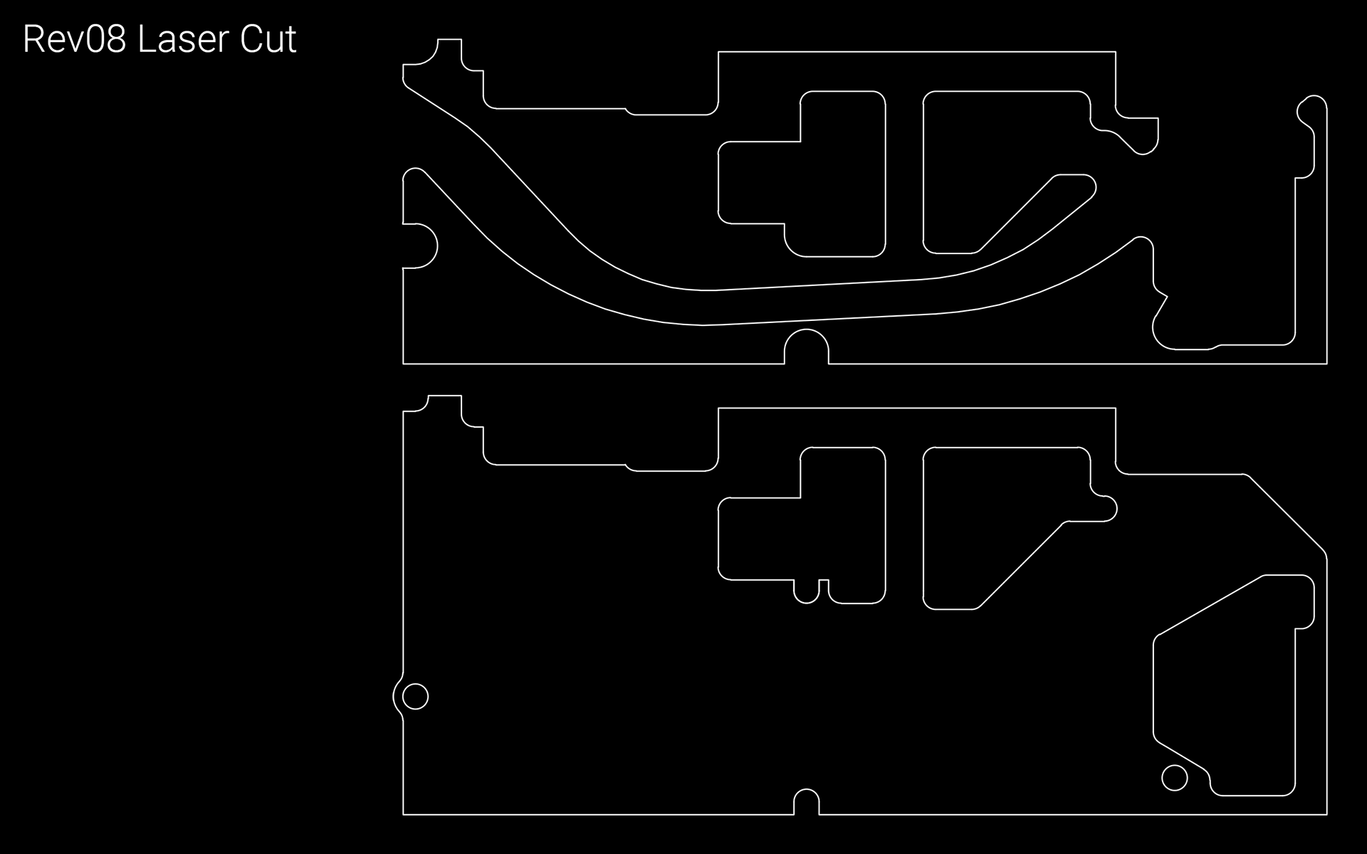
Rev08 added a 0.5mm cutout for the GPU to make the heatpipes sit at a similar height to the original. I also made a version for laser cutting, in case I couldn't get it CNC'd.
January 2nd, 2019
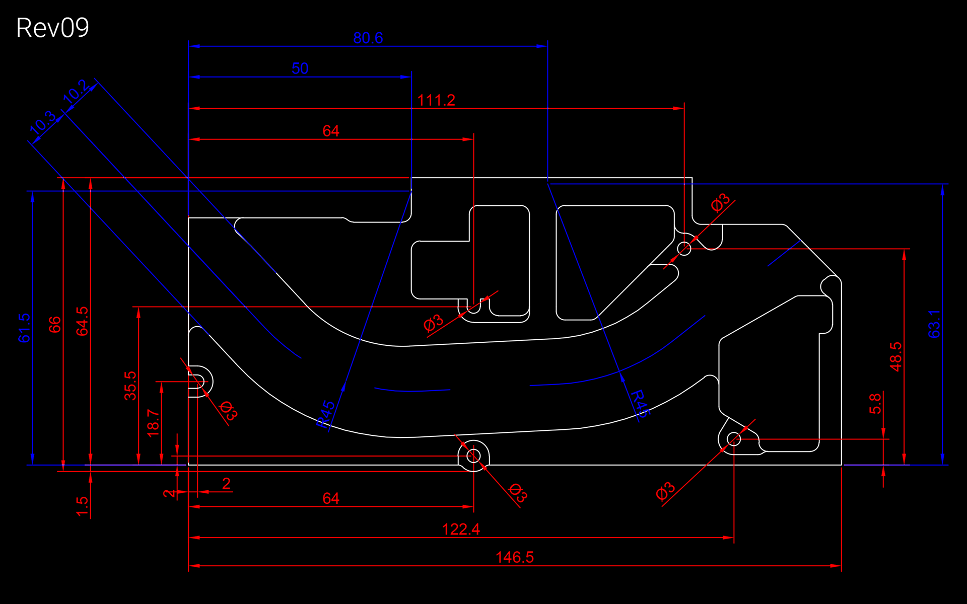
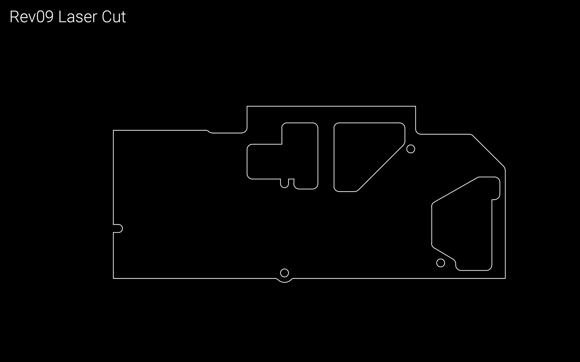
Sent off for prices for both CNCing and laser cutting. As with Rev09, I made two versions. Laser cutting proved cheaper, so I went forward on the assumption that I'd be doing that. To reduce material and cutting costs, I removed the top left of the plate, as the extra mount isn't necessary.
January 9th, 2019
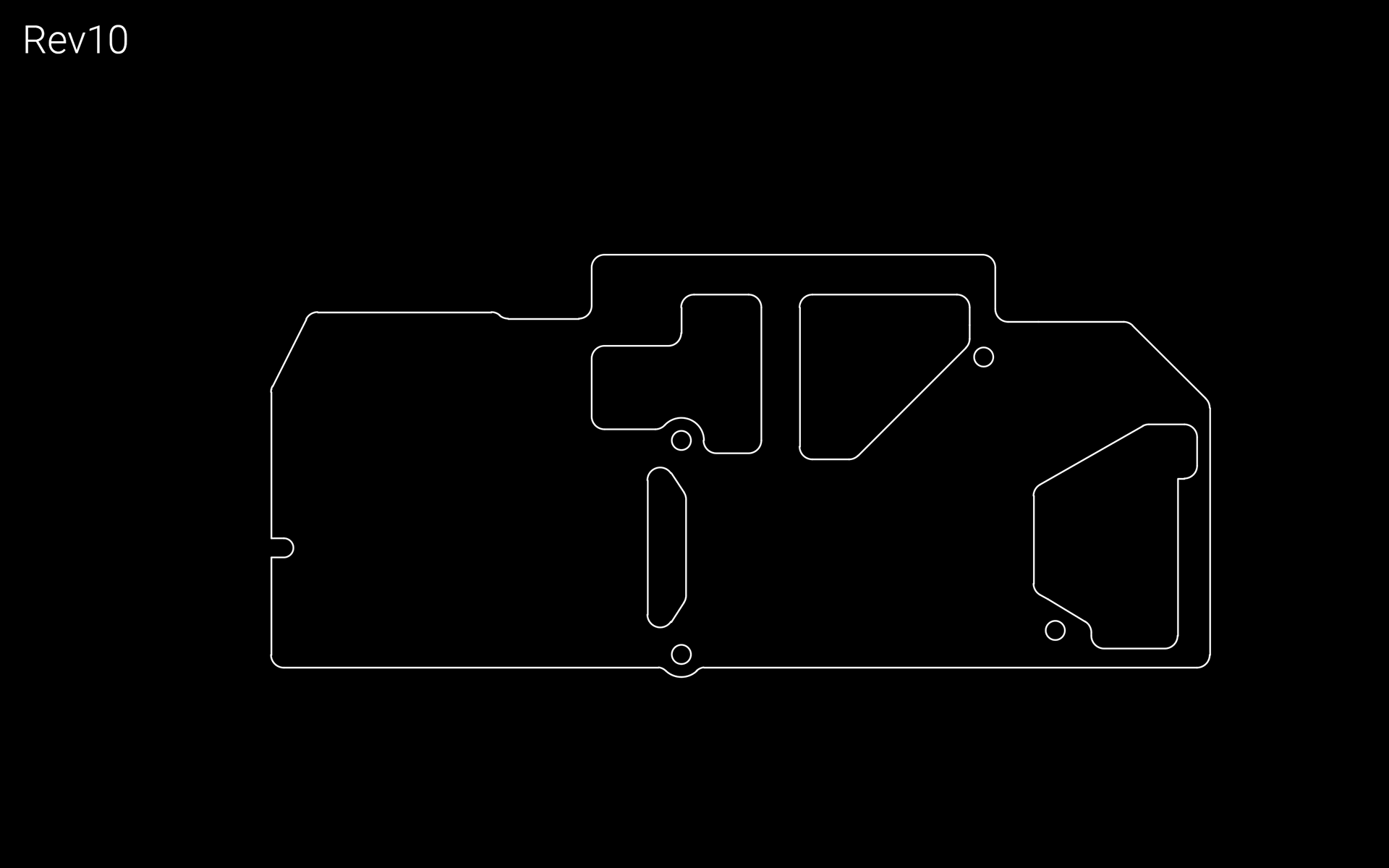
Rev10 added a cutout between the CPU and GPU, to try and decrease the CPU temperature's influence on the GPU.
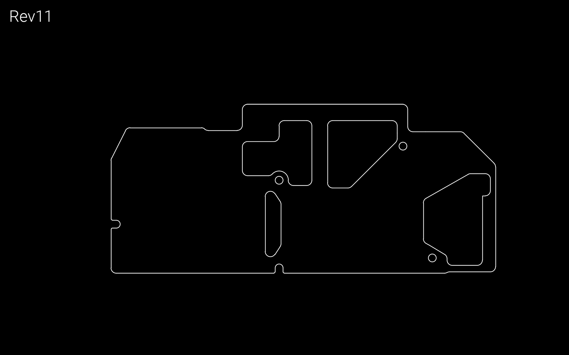
January 14th, 2019
Rev11 changed the bottom mounting hole to a slot, and small adjustments were made to ensure it fitted before ordering.
February 4th, 2019
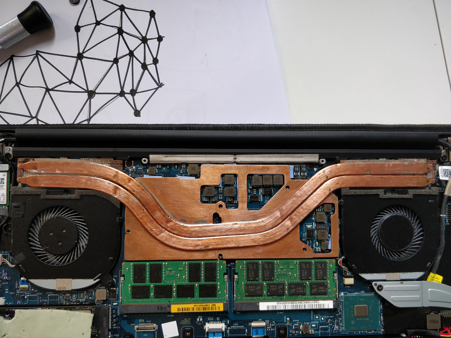
Laser cut copper turned up. Fitted pretty perfectly, and 1mm thermal pads kept mounting pressure pretty consistent. Back panel fits (with a bit of persuasion) with this plate and the stock heatpipes and fins.
February 5th, 2019
Spring screws turned up, and the components were test fitted before soldering. Spring screws prevented the back panel from fitting, without putting an uncomfortable force on the tiny screws on the back of the panel.
February 13th, 2019
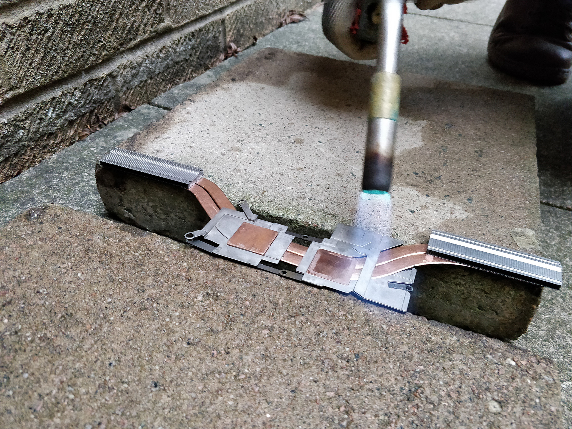
Soldered it all together with a blow lamp. Unfortunately, I didn't line up the heatpipes that well, so they had to be re-positioned. The plumbing blow lamp that I was using was too hot, and made the heatpipes swell up before the solder could melt properly.
February 15th, 2019
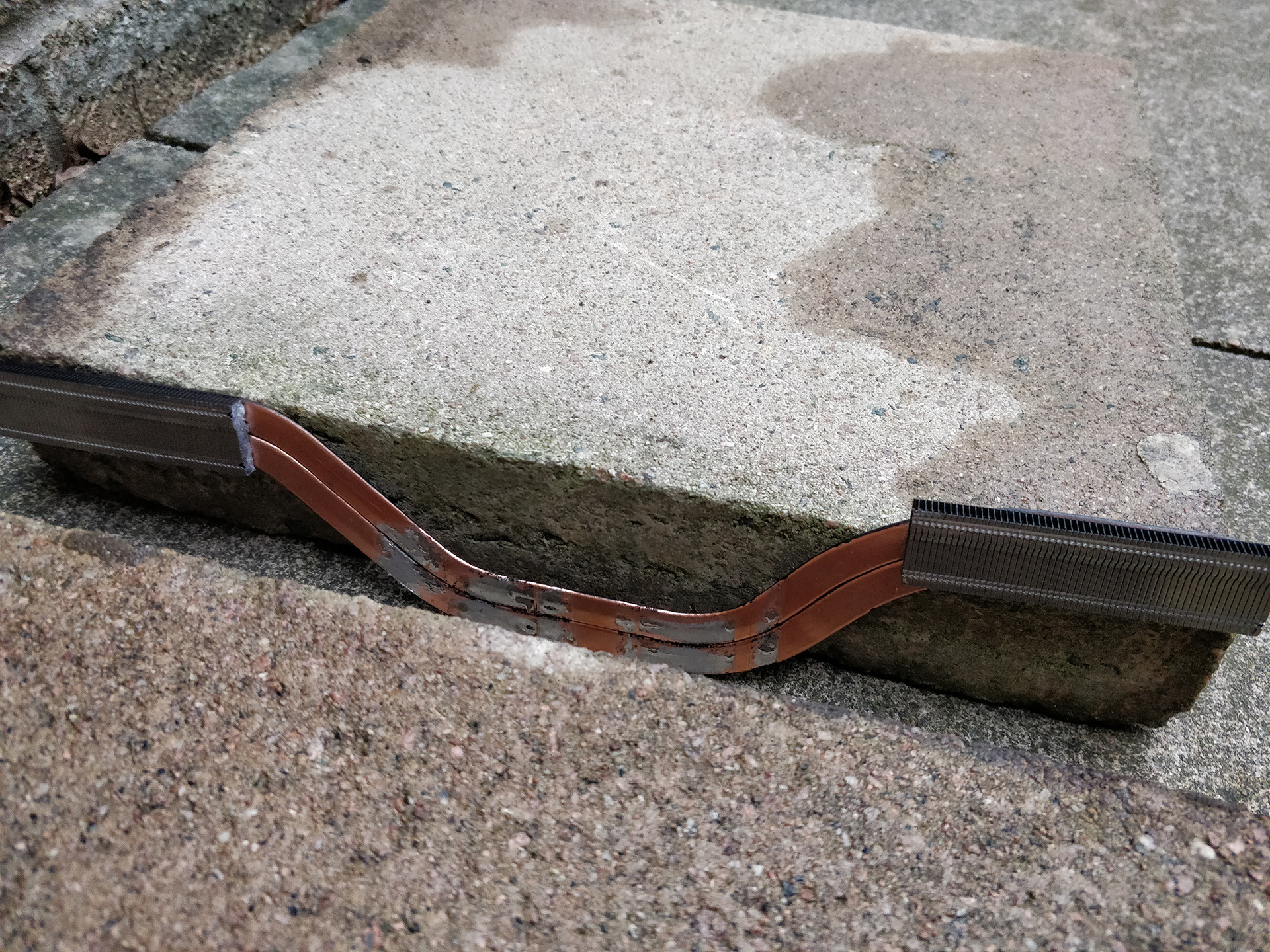
Resoldered it all, flattened out the pipes, and used a kitchen blow torch (the kind meant for caramelising, and such) to make solder without inflating the pipes. Got all of the components into the right place, and started thermal testing (Results of which can be seen here).
February 17th, 2019
Tried messing with the placement of the pipes to get the back panel to sit properly, but that wasn't working. Ended up moving them a bit too far. The fins that I replaced the stock ones with are too tall, so coupled with the heatpipes pushing on the middle, they prevent the back panel from closing properly without warping.
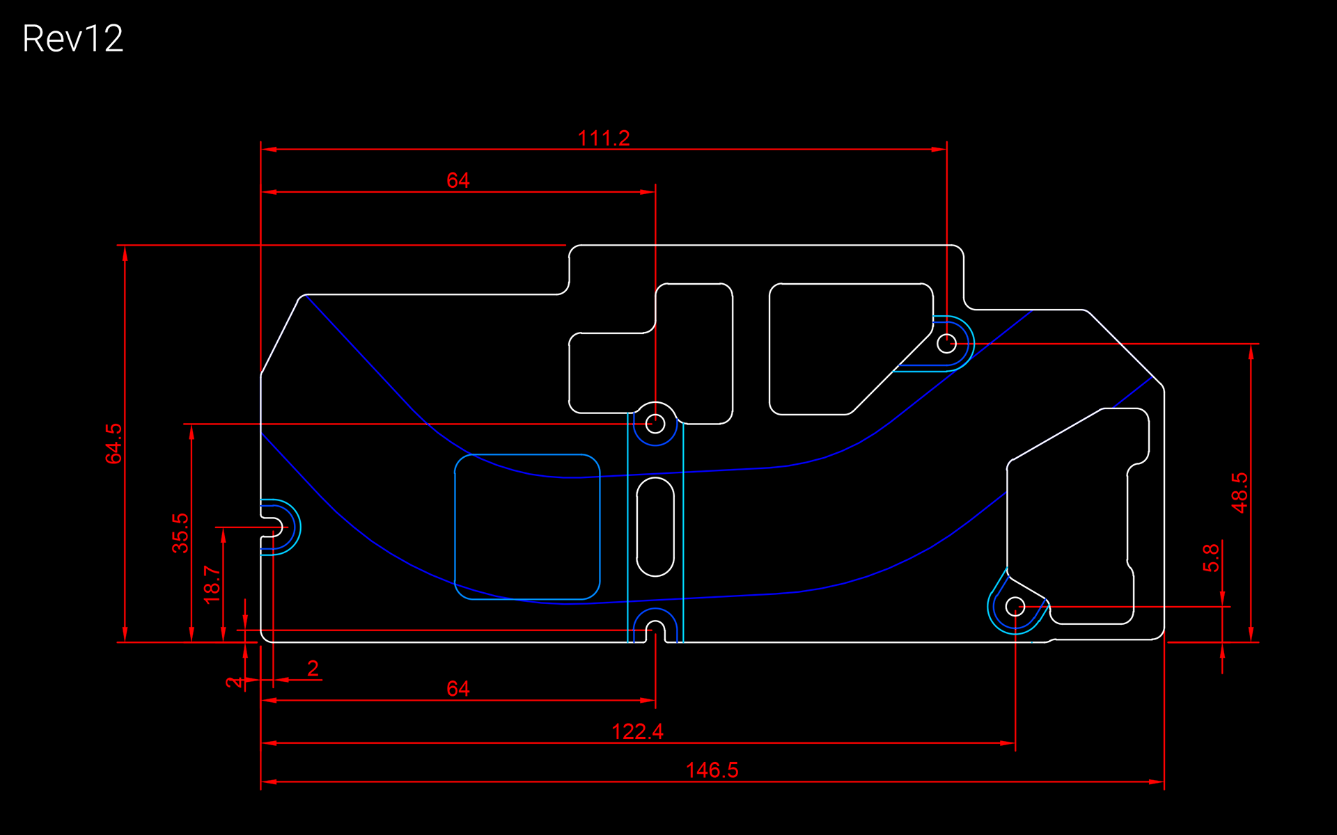
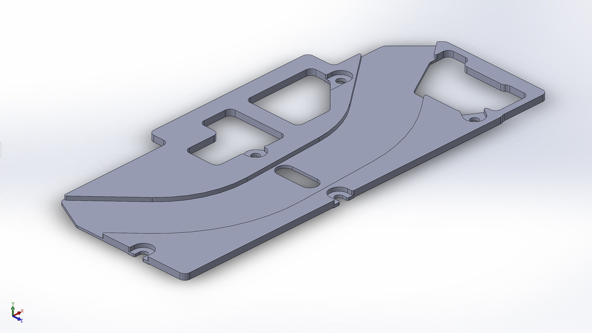
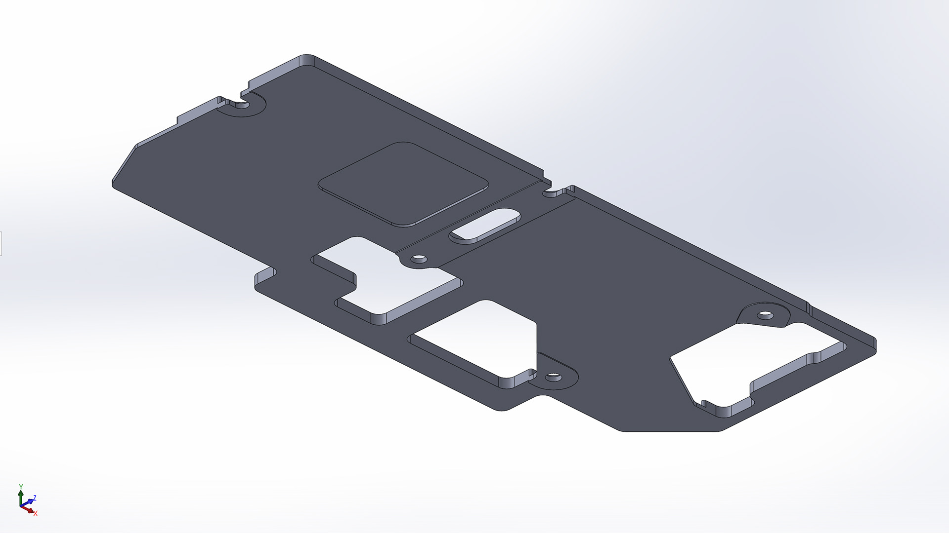
February 24th, 2019
Rev12 addresses the issues from Rev11, and corrects a few dimensions to make it fit more closely around the taller components. It uses the same heights as the shims on the original heatsink (0.3mm over the GPU, 0.8mm over the CPU), but still increases the thermal mass and covers the VRMs. I'm currently looking at sourcing copper versions of the original fin stacks, and getting the plate CNC'd without breaking the bank.
A much less pretty and "concise" version of events can be found at the below link, where I discuss the details of the project a bit further.